


CAUTION! Care should be taken in using capacitors and equipment at voltages in excess of 50. Lethal voltages can be retained for many hours.
LEAKAGE
These capacitors depend on their operation for a thin insulation film formed by the electrolytic action of the applied voltage. When they are unused for a period of time this film is lost and the leakage current rises and the capacitance falls.
There is always some current leakage through such capacitors and the value depends on the voltage, the capacitance value and temperature. The current is always higher after initial application of voltage even for capacitors in regular use.
The table below shows maximum values for new 1968 components sold by Radiospares. The figures relate to leakage 10 minutes after application of voltage; it is probable that these relate to a temperature of 70oC.
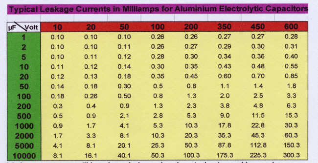
This table is based on the formula; Current in micro-amps = 0.08CV+100 for capacitors of working voltage < 100V and 0.05CV +250 for working voltages above 100V. C is in microfarads and V is in Volts.
Modern components will have lower leakages than those in the above table – see later.
REFORMING
Capacitors that have been out of use, whether in equipment or held in stock need to be reformed by the careful application of voltage so that the film is restored.
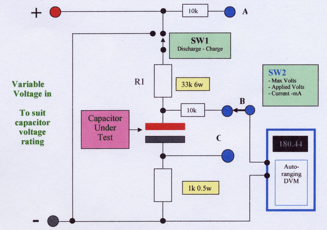
I use the circuit below to reform components of all voltages and values.
DESCRIPTION
A dc voltage is applied to the capacitor through a current limiting resistor, R1. This prevents damage to the capacitor and to the voltage source if the capacitor is faulty. Otherwise, should the capacitor have a large leakage application of voltage could cause the electrolyte inside the case to vaporise and the can to explode.
SW1 is used to charge and discharge the capacitor via R1. The discharge is essential at the end of the test for safety when high voltages are used. It also can be used to repeat tests of leakage current measurements with time after first application of the voltage.
A single voltmeter and 3-way switch can monitor the maximum (final) voltage, the voltage across the capacitor and the leakage current. 10k ohm resistors are included in the connections to prevent excessive current should the leads to the DVM be shorted or it operated on a current range.
Although it is convenient to use a single auto-ranging meter, separate meters or a plug arrangement may be used.
The values shown are suitable for most reforming operations but R1 may be reduced to as low as 4k7 when dealing with large capacitance, low voltage components. The power rating must be sufficient to withstand the capacitor being short-circuit.
OPERATION
Set SW1 to “Discharge”.
Select a voltage of about 25% of the capacitor’s voltage rating and monitor with SW2 at “A”.
Switch SW2 to “C”
Switch SW1 to “Charge”
Observe the leakage current read on the meter (1 volt = 1 mA). This will normally start to fall after a few seconds. Occasionally it may rise and then fall back again. If it remains steady or continues to rise after 5 minutes, it is probable that it will not be possible to reform the capacitor.
Switching SW2 to “B” shows the voltage across the capacitor.
If the current has fallen to below that indicated in the above table, repeat operations 1 to 6 with higher voltages – two stages of 60% and 100% are usually adequate.
On final voltage, check that the leakage current is acceptable. Typically a reformed unit will have a leakage of about 20% of those in the above table. (The table is for 70oC rather than 20oC for the bench tests). Ideally leave it reforming until there is no further decrease in the leakage current. However, on large values reforming may take several hours and this may be done in the equipment if the initial leakage has been reduced sufficiently.
Discharge the capacitor by switching SW1 to “Discharge” before disconnecting it and handling.
Multi-section capacitors can also be reformed by connecting the sections in parallel. If they have different voltage ratings then apply a voltage that does not exceed the lowest voltage rating.
Modern Capacitors
For comparison, the leakage for modern aluminium electrolytic capacitors after 5 minutes of applying rated voltage is given below. This is based on leakage of (0.3CV)0.7 + 4 micro amps.
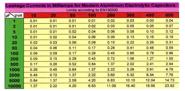
These leakages are below 10% of those in the first table. However I have found that even vintage capacitors correctly reformed achieve figures very similar to these lower ones.
CAPACITOR LIFE
All aluminium electrolytic capacitors have a limited life which depends on how they are used. The critical parameter is temperature of the unit. This is a function of ambient temperature, ripple current and cooling.
The following figures are abstracted from a manufacturer’s specification for typical standard sized industrial grade components.
A board-mounted unit operating at the rated ripple current at an ambient temperature of 40oC has an estimated life of 250,000 hours or some 28 years of continuous operation. If the ambient temperature is raised to 60oC the life is reduced to 50,000 hours and at 85oC a mere 4000 hours (less than 6 months).
Increasing the ripple current by 50% above the rated value halves the service life. Operating frequency also impacts on the service life. The ripple current rating must be increased by 40% for frequencies of 10kHz and above, and at 400Hz by 20%.
It is noted that the maximum life expected is 28 years and even special units cannot offer a life of more that 10,000 hours at 85oC.
In placing electrolytic capacitors it is therefore good practice to locate them as far as possible from heat sources. Because maximum ripple currents occur in power supply applications, it is all too common to find them located next to the power transformer or output valves! This may be convenient for construction but not conducive to a long life.
www.Electrojumble.org 2009